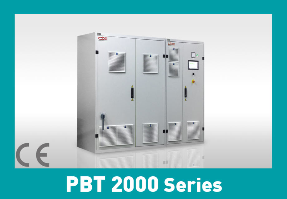
PBT 2000 Series : Eco Series - Power Battery Pack Test Equipment
Intro:
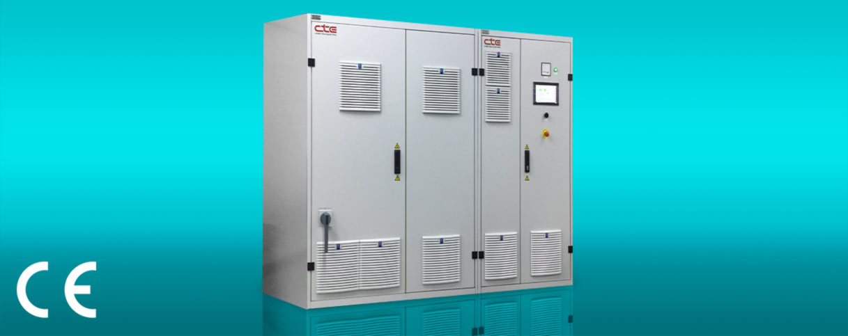
PBT 2000 series is specially designed for Electric Vehicle battery test. It rapidly simulates electric vehicle in actual on-road driving conditions and obtains the performance of battery operation to ensure its applicability. The discharge energy during the testing is effectively recycled to improve electrical efficiency and reduce the burden of air-conditioning in the testing environment.
- Max. output is 500kW/1000V/2000A.
- The discharged energy recycling efficiency is able to reach up to 95%.
- Built-in FUDS, DST, HPPC and many other international drive simulation testing standards, also supports custom drive cycles profile.
- Possesses the dual functionality for performing battery testing and battery simulations.
- Supports 2 ranges of current output and measurements.
- PC control and panel control dual-mode operations, touch controls are supported by panel operation.
- Meets EN ISO 13849-1 performance level D.
| Model | PBT 2000 Series |
| AC Power | Customized According To Client Needs |
| Power Factor | > 0.99 |
VoltageMaximum Resolusion Accuracy | Depend on Spec 16 bit ± 0.1% F.S. |
Constant CurrentMaximum Charge/Discharge Current Range Resolution Accuracy | Depend on Spec 2 (Option) 16 bit ± 0.1% F.S. |
| Data Recording Time | 100ms (Option:10ms) |
| Switch Time between Charge and Discharge | <2ms |
| Drive Simulation | FUDS, DST ,HPPC, Custom Patterns |
| Bidirectional Converter Efficiency | Up to 95% |
| Communication Interface | Ethernet |
| Optional Features | Constant Resistance、DCIR Measurement、ACIR Measurement、BMS & Gas Gauge Data Collection、Chamber Integration、Data Analyzer、Parallel Connections among Channels |
| Accessory | BMS & Gas Gauge Data Collector、Auxiliary Voltage、Auxiliary Temperature、Chamber、Battery Connecting Cable、Parallel Connection Module、Power Distribution Switch Box、Power Distribution Unit |
*Accept customized request
| Model | Power (kW) | Voltage(V) | Current (A) | Model | Power (kW) | Voltage(V) | Current (A) |
| PBT 2000 300-60-200 | 60 | 300 | 200 | PBT 2000 1000-160-1000 | 160 | 1000 | 1000 |
| PBT 2000 300-60-600 | 60 | 300 | 600 | PBT 2000 600-250-600 | 250 | 600 | 600 |
| PBT 2000 300-60-1000 | 60 | 300 | 1000 | PBT 2000 600-250-1000 | 250 | 600 | 1000 |
| PBT 2000 300-100-600 | 100 | 300 | 600 | PBT 2000 800-250-600 | 250 | 800 | 600 |
| PBT 2000 300-100-1000 | 100 | 300 | 1000 | PBT 2000 800-250-1000 | 250 | 800 | 1000 |
| PBT 2000 600-100-200 | 100 | 600 | 200 | PBT 2000 1000-250-600 | 250 | 1000 | 600 |
| PBT 2000 600-100-600 | 100 | 600 | 600 | PBT 2000 1000-250-1000 | 250 | 1000 | 1000 |
| PBT 2000 600-100-1000 | 100 | 600 | 1000 | PBT 2000 600-320-600 | 320 | 600 | 600 |
| PBT 2000 800-100-200 | 100 | 800 | 200 | PBT 2000 600-320-1000 | 320 | 600 | 1000 |
| PBT 2000 800-100-600 | 100 | 800 | 600 | PBT 2000 800-320-600 | 320 | 800 | 600 |
| PBT 2000 800-100-1000 | 100 | 800 | 1000 | PBT 2000 800-320-1000 | 320 | 800 | 1000 |
| PBT 2000 1000-100-200 | 100 | 1000 | 200 | PBT 2000 1000-320-600 | 320 | 1000 | 600 |
| PBT 2000 1000-100-600 | 100 | 1000 | 600 | PBT 2000 1000-320-1000 | 320 | 1000 | 1000 |
| PBT 2000 1000-100-1000 | 100 | 1000 | 1000 | PBT 2000 600-400-1000 | 400 | 600 | 1000 |
| PBT 2000 600-160-600 | 160 | 600 | 600 | PBT 2000 800-400-1000 | 400 | 800 | 1000 |
| PBT 2000 600-160-1000 | 160 | 600 | 1000 | PBT 2000 1000-400-600 | 400 | 1000 | 600 |
| PBT 2000 800-160-200 | 160 | 800 | 200 | PBT 2000 1000-400-1000 | 400 | 1000 | 1000 |
| PBT 2000 800-160-600 | 160 | 800 | 600 | PBT 2000 600-500-1000 | 500 | 600 | 1000 |
| PBT 2000 800-160-1000 | 160 | 800 | 1000 | PBT 2000 800-500-1000 | 500 | 800 | 1000 |
| PBT 2000 1000-160-200 | 160 | 1000 | 200 | PBT 2000 1000-500-600 | 500 | 1000 | 600 |
| PBT 2000 1000-160-600 | 160 | 1000 | 600 | PBT 2000 1000-500-1000 | 500 | 1000 | 1000 |
Constant Resistance
DCIR Measurement
High-power battery module DC internal resistance
ACIR Measurement
High-power battery module AC internal resistance
Parallel Connections among Channels
BMS & Gas Gauge Data Collection
During battery modules/ packs testing, the Gas Gauge/ BMS data is retrieved and recorded.
The data obtained can be used as the condition for program step change or providing protection.
1. Supports communication protocols such as SMBus, I2C, HDQ etc. for IT batteries and Modbus, CANBus etc. for power batteries.
2. Supports CAN .dbc file editing and import.
Chamber Integration
The synchronous control of chambers can be achieved during the testing processes.
Temperature and humidity levels can be adjusted to simulate different environments for measuring the battery’s performance.
Data Analysis
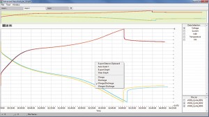
With data analysis feature, a variety of test data presentations could be adjusted according to the needs of researchers, such as text and graphical reports, self-defined X and Y-axis parameters on graphs and graphs zoom-in / zoom-out. It also helps researchers to easily analyze the data from cycle test. Data from each cycle can be superimposed and drew on a single chart to produce a lifecycle test report. Evaluating test results and finding variation are easy! Moreover, test data can be exported in csv format and manipulated in the third-party software that researchers are familiar with, improving the data usability.
BMS/ Gas Gauge Data Collector
Records the static/ dynamic parameters of the BMS in energy/ power batteries. It supports SMBus, I2C, HDQ, Modbus, CANbus and other communication protocols that are commonly used in energy and power batteries, and it is scalable. With GDA 300, users are allowed to define customized parameters as step cutoff condition while running battery test. Additional parameters can also be defined by researchers to collect and analyze advanced data.
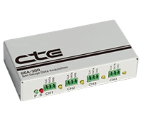
| Model | iBox - G | GDA-300 |
| CH/ per Unit | 8CH | 4CH |
| CH/ per System | 256CH | 128CH |
| Mechanism Design | Rack/ Portable | Rack/ Portable |
| Communication Protocols (Battery) | SMBus/ I2C / HDQ | SMBus/ I2C / HDQ |
| Communication Protocols (PC) | Ethernet/ Wifi | RS-485 |
| Communication Speed | 2Sec / 8CH* | 5Sec / 16CH |
| Number of parameters | 47 | 47 |
| Temperature Classification | 0~60°C | 0~60°C |
| SmartCHarge | Yes | Yes |
| SBS Write | Yes | Yes |
| Gauge Condition | Yes | Yes |
*iBox-G only
Auxiliary Voltage/ Auxiliary Temperature
Auxiliary voltage and auxiliary temperature are for collecting the voltage and temperature data of a single cell in the battery pack. Collected data can be used as step cutoff conditions while running the battery test, improving the flexibility of the production line and laboratory.
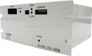
| Model | Auxiliary Voltage ES-100B |
| Channels | 24 |
| Measurement Range | ±64V,±32V,±8V |
| Measurement Resolution | 16 bit |
| Accuracy | 0.02% F.S. |
| Data Recording Time | 100ms (24CH) |
| Model | Auxiliary Temperature ET-100B |
| Channels | 24 |
| Measurement Range* | -50°C~125°C |
| Measurement Resolution | 0.1°C |
| Accuracy | ±1°C (-40°C~90°C) |
| Temperature Sensor | Thermistor |
| Supported Type | 103JT |
| Data Recording Time | 100ms (24CH) |
| Model | Auxiliary Temperature ET-100C | |||
| Channels | 16CH | 8CH | 8CH | 16CH |
| Scanning Speed | 4CH/s (16CH/4s) | 4CH/s (16CH/4s) | 4CH/s (16CH/4s) | 4CH/s (16CH/4s) |
| Accuracy | ±1°C | ±1°C | ±1°C | ±1°C |
| Resolution | 0.1°C | 0.1°C | 0.1°C | 0.1°C |
| Temperature Sensor | Thermocouple | RTD | Thermistor | Diode |
| Supported Type | Type J, K, E, N, R, S, T, B | PT-10, PT-50, PT-100, PT-200, PT-500, PT-1000, NI-120 | 44004 2.252kΩ, 44005 3kΩ, 44007 5kΩ,44006 10kΩ, 44008 30kΩ | 3904 |
| Measurement Range* | -265~800°C | -200~800°C | -40~150°C | -60~130°C |
*Depend on chosen thermal sensors
Chamber
We collaborate with several 3-rd party chamber manufacturers such as Espec, Terchy, Giant Force, and TATO, and integrate their products into our system. Thus, users are capable of controlling chamber directly with iBest software.
Battery Connecting Cable
Parallel Connection Module
Power Distribution Switch Box
Power Distribution Unit
You may also like…
